Manual
Login
Our 3D CAD supplier models have been moved to 3Dfindit.com, the new visual search engine for 3D CAD, CAE & BIM models.
You can log in there with your existing account of this site.
The content remains free of charge.

Top Links
Manual
 |
The Measure dialog is subdivided into the fields Element 1, Element 2 and Result and Constraints.
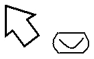
By calling the Measure command the mouse pointer gets a object related geometry symbol in the 3D view , which is signalizing the type of the touched element.
After you have clicked consecutively on two drawing elements (area, edge or bore etc.) in the 3D view, a Symbol is displayed in each of the fields Element 1 and Element 2.
In the following the possible geometry symbols are shown:


In the example, the user has clicked on two neighboring faces of the hex nut.
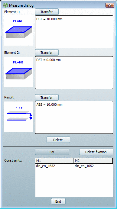


The two faces are at a specific distance of 10 mm, as shown symbolically in the Result area. The measure of distance (ABS = 10.000 mm) is displayed to the right of it.
With planar, parallel planes the command is available.
Changing the table row the measurement in the 3D view will persist.
With you can delete the constraint.
The command can be used during the classification procedure of native parts.
Detailed information can be found under Section 5.13.5.3.1, “Value take-over from the Measure dialog window ”.
