Manual
Login
Our 3D CAD supplier models have been moved to 3Dfindit.com, the new visual search engine for 3D CAD, CAE & BIM models.
You can log in there with your existing account of this site.
The content remains free of charge.

Top Links
Manual
 |
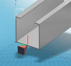
The connection points must be created in such a manner that the connection parts have the same direction. This means that a connection element may not be turned 180° because then the open side of the cable duct must always be on the same side.
This is reached because the red axis always points upwards.
The following figure shows two parts that need to be connected:
|
|
|
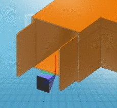
Result: The red axes are on top of each other, the green and blue axes point in the opposite direction
|

In order for the fences to be able to move around the hinge, the connection points must be in opposite directions.
In this example, the red coordinate axes are also on top of each other, so the respective connection point of the right and left fence must be opposite each other.
One connection point points upwards, the other downwards.
One of the red axes of the coordinate system points out of the fence, the other into it.


The position of a lever depends on the orientation of the connection point.
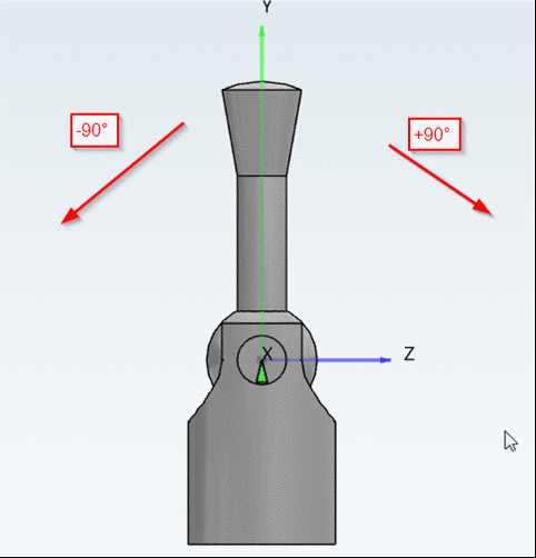
If, for example, the angle of the connection point is set on 0° (by default), this may lead to a wrong default position of the movable element.
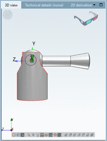
However, this can be corrected later in the Configurator, in dialog Rule properties, but much simpler (and most of all without source of error, which may lead to export problems) it would be to set the desired default position via "Angle" setting in the Sketcher.

