Manual
Login
Our 3D CAD supplier models have been moved to 3Dfindit.com, the new visual search engine for 3D CAD, CAE & BIM models.
You can log in there with your existing account of this site.
The content remains free of charge.

Top Links
Manual
 |
The following example shows how a configuration is assembled step-by-step and individually in the PARTdataManager.
![[Note]](/community/externals/manuals/%24%7Bb2b:MANUALPATH/images/note.png) |
Note |
|---|---|
|
You can follow the example if you have installed the training.cip. (Training/assembly/hinge/hinge_asmcfg.prj) A detailed description on this can be found in Example 2. | |
-
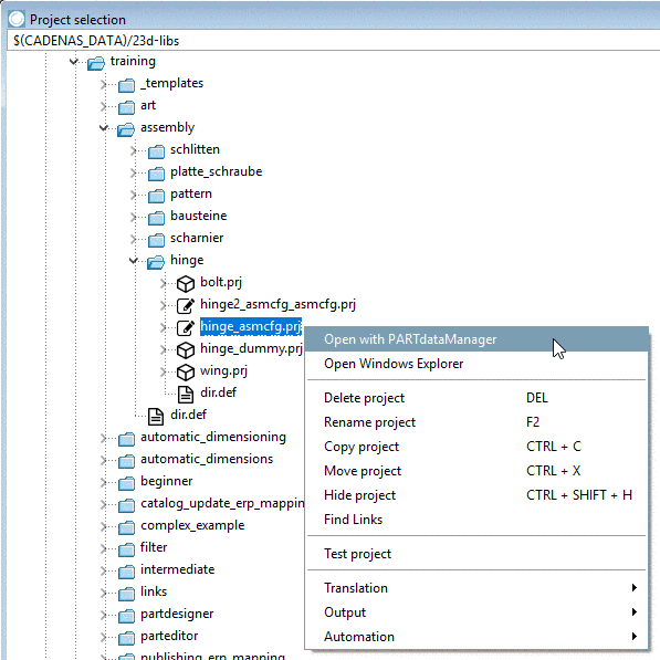
In PARTproject, select a configuration and call the context menu command Open with PARTdataManager.
-
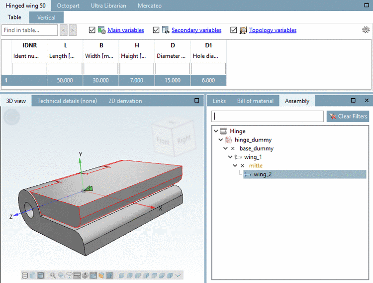
First in the docking window Assembly, in the tree view on the left, only the assembly name is displayed and on the right the dummy starter part.
The configuration elements are already applied, however they still need to be selected and/or activated.
-
Click on the displayed part (here in following exemplary figure "hinge_dummy").
-> The part is shown with red text color, as it is not yet determined uniquely. In the table there are several characteristics, from which you have to select one.
-
Note In the Tree view, you can see the possible Connection points below the parts - as long as there are further connection parts available. These are depicted as small green (or red) pyramid symbols in the 3D view.
At each connection point, assembly components from the Option list can be added - if provided.
The insertion points in the Tree view are color-coded:
With the described way you can insert individual elements until all suggestions have been covered. Then there are only connections with black font.
If you want to know the exact position of a certain connection point in the part, mark its name in the Assembly, in the Tree view. Then the respective pyramid symbol is shown in red color in the 3D view.
-
Select the connection point (if not yet selected).
-> Available connection points are displayed.
-> Available parts are listed (here in this example at this place only one).
-
Click on "wing1" and select a table row.
-> The connection point "mitte" and possible parts available for the assembly creation are shown.
-> The part is displayed in the 3D view.
-
Click on another part and then on a table row.
-> The connection point is shown in yellow. I.e. there are still more parts available for this connection point.
-
Once again select the connection point "mitte".
-> Other still available parts are displayed.
-
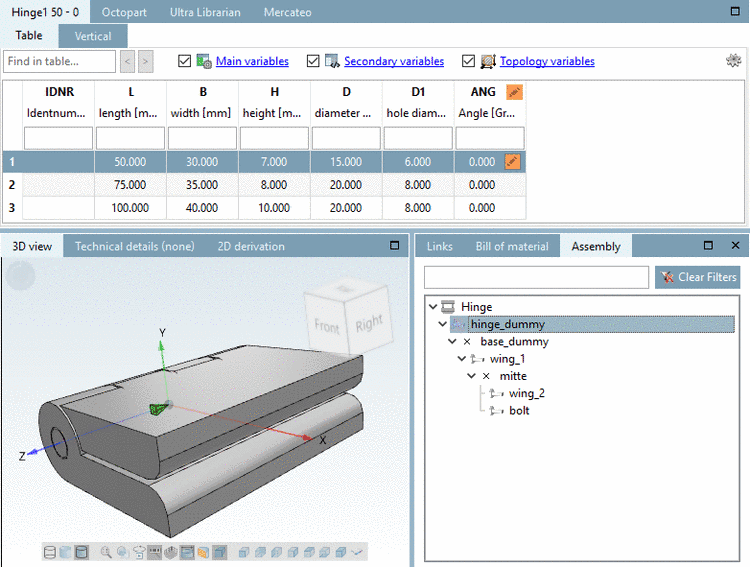
In the described way, insert all offered parts into the assembly.
Once the assembly is completed, meaning no more parts available for insertion, everything is displayed in black font color.