Manual
Login
Our 3D CAD supplier models have been moved to 3Dfindit.com, the new visual search engine for 3D CAD, CAE & BIM models.
You can log in there with your existing account of this site.
The content remains free of charge.

Top Links
Manual
 |
-
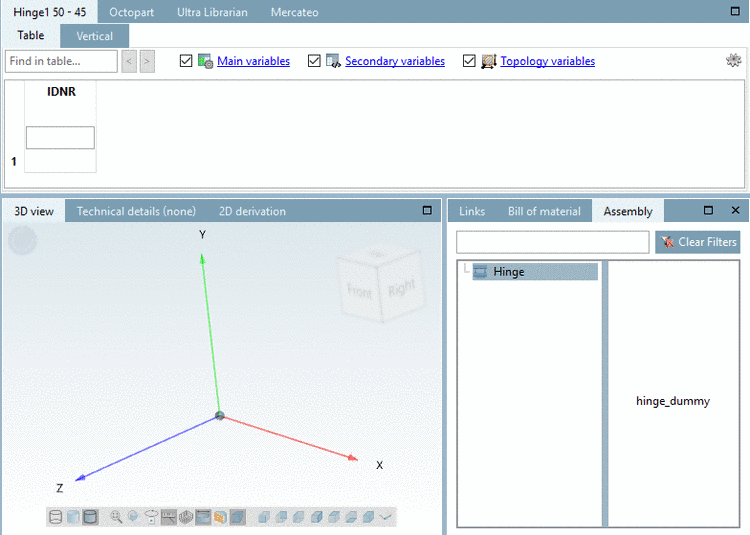
In the docking window Assembly, click on the assembly's name (here in this example "Hinge").
-> The starter element is displayed (without picture, as it has no geometry).
-
-> The starter element is displayed with red text color, as it is not yet determined uniquely. In the table there are several characteristics, from where you have to select one.
-
Select a table row (a characteristic). This step is mandatory, only then the build up process continues!
-> The connection point is displayed (here in this example "base_dummy"; it is only one, it could be more as well).
-> At the same time you can see the connection point in the 3D view.
Green means that there is at least one connection part, but none is yet selected.
-
Click on the connection point.
-> Possible parts are shown on the right. In this case only one is possible.
-
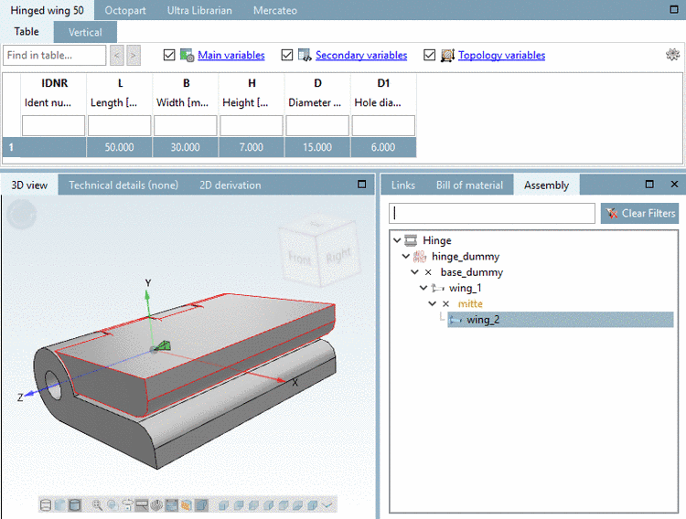
-> The connection point "mitte" and parts available for the assembly are now displayed.
-> The part is shown in the 3D view.
-
-> The connection point is shown in yellow. I.e. there are more parts available for this connection point.
-
Once again click on the connection point.
-> Other parts still available are shown.
-
In the described way, insert all listed parts in the assembly.
Once the assembly is completed, meaning there are no further parts to insert, everything is displayed in black text color.
-
In the docking window Assembly, select "hinge_dummy".
-> The configuration is displayed with table. (Dummy table will be used as assembly table later.)
![[Note]](/community/externals/manuals/%24%7Bb2b:MANUALPATH/images/note.png)


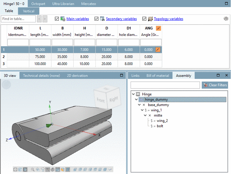

When selecting a table row the assembly is built up accordingly.
(If there is only one row available, the row selection can be left out and the part is immediately inserted.)
The angularity can be controlled via variable ANG. In above figure 90°.
In the next step a template is created from the assembly configuration.
