Manual
Login
Our 3D CAD supplier models have been moved to 3Dfindit.com, the new visual search engine for 3D CAD, CAE & BIM models.
You can log in there with your existing account of this site.
The content remains free of charge.

Top Links
Manual
 |
- 3.1.20.6.2.2.1. Zoom all
- 3.1.20.6.2.2.2. Transfer to PARTbom/ Selected parts
- 3.1.20.6.2.2.3. Transparency
- 3.1.20.6.2.2.4. Part comparison
- 3.1.20.6.2.2.5. Animation / Set rotation center
- 3.1.20.6.2.2.6. Views
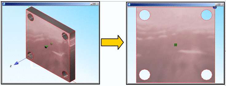
- 3.1.20.6.2.2.7. Normal to face
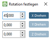
- 3.1.20.6.2.2.8. Enter rotation angle
- 3.1.20.6.2.2.9. Define section cut...
- 3.1.20.6.2.2.10. Measurement of 3D parts
- 3.1.20.6.2.2.11. Measuring grid
- 3.1.20.6.2.2.12. Print
- 3.1.20.6.2.2.13. Specific commands for assemblies

![[Note]](/community/externals/manuals/%24%7Bb2b:MANUALPATH/images/note.png) |
Note |
|---|---|
|
Set the assignment of keys under PARTdataManager - > Extras -> Settings... -> 3D settings -> Mouse and keyboard. Detailed information on this can be found under Section 3.3.8.4.2, “ Mouse and keyboard assignment”. | |
With the Zoom all button you bring the display of the part onto a balanced measurement. The part is large enough, but still does not protrude over the 3D view window during rotation. If the option Explicit zoom has been set (see Section 3.3.8.4.1, “ Handling ”) the display within the window is maximally enlarged.


You can transfer parts to your CAD system and alternatively to PARTbom.
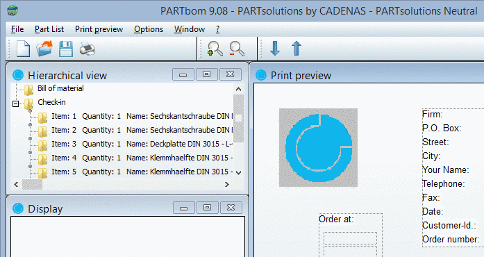
PARTbom (bom = bill of material) is an administration tool in order to create lists of bom for orders. A detailed description of PARTbom you can find under Section 3.2, “ PARTbom ”.
You can both transfer single parts and a selection of different individual parts of an assembly:

Subsequent to your selection in the context menu click on Selected parts -> Transfer to PARTbom.
-> A dialog box where you adjust the number of parts is displayed. Adjust the number and confirm with .

-> Afterwards PARTbom opens with the following message:

Choose an option and confirm with .
Transparency: Regulate the transparency of a solid
Via slider, you can adjust the transparency stepless from fully visible to invisible.

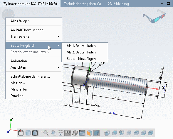
Detailed information on the part comparison can be found under Section 3.1.6.10, “ Part comparison ”.
This command starts an automated rotational movementof the current solid.

The command
exists in the context menu as well as in the 3D toolbar  .
.
The rotation happens around the rotation center.
With a right-click on any point inside the part and the Set rotation center command (also inside the context menu) you set the rotation center of the animation.
In order to stop the animation, click on the Animation command again or on any place within the 3D window.
Under Views, you can find 6 axis related perspectives and an Iso, Di and Trimetric view (Perspective projection).


Select a sectional plane and the desired offset in relation to zero level. Depending on the algebraic sign an offset in positive or negative direction results.

More details can be found under Section 3.1.7.6.7, “ Define section cut... ”.
You have the opportunity to print the 3D view of the part/assembly.
When clicking on the command the respective settings dialog box of your operation system opens.

Context menus of parts and assemblies slightly differ. At assemblies the context menu depends on whether the focus is inside or outside of the assembly.
-
Assembly (Call outside of the assembly):
A menu with the functions Search..., Transfer to PARTbom, Transparency is opened.
-
Note The search function concerns the docking window Assembly! See Section 3.1.20.6.2.7, “Context menu commands in docking window "Assembly"”.
Transfer to PARTbom: See Section 3.1.20.6.2.2.2, “ Transfer to PARTbom/ Selected parts ”.
Transparency: See Section 3.1.20.6.2.2.3, “ Transparency ”.
-
-
Exact assembly name (e.g. Gehaeuse....) (call within assembly):
A submenu with the functions Zoom, Delete, Transfer to PARTbom, Transparency is opened.
-
Zoom: Catches the selected part; in contrary to Zoom all, which concerns the whole assembly.
-
Transfer to PARTbom: See Section 3.1.20.6.2.2.2, “ Transfer to PARTbom/ Selected parts ”.
Transparency: See Section 3.1.20.6.2.2.3, “ Transparency ”.
-


